

This guide walks through how we review a pump or valve housing alongside your engineers: what we look at at each stage, why it matters for a sealed, pressure-containing part, and what to have ready when we talk. For the broader picture of replacing metal with engineering thermoplastics, see Metal-to-Plastic Conversion: Welding and Sealing Thermoplastic Assemblies.
Why Involve the Joining Process Early in a Plastic Pump or Valve Design?
Once the mold is built, the joint is mostly locked in. Groove width and depth, wall stock behind the seam, room for displaced melt, insert positions, and surfaces the fixture can push on are all molded features. If they are designed around a gasket or an adhesive and the program later moves to welding, the usual result is tool changes or a compromised joint.
Reviewing the housing with Emabond while the CAD is still moving lets the joint be sized for the actual pressure load, keeps flash away from functional areas, and makes sure the part can be supported and welded the way it will be built in production.
Stage 1: Concept — Where Will the Housing Seal, and What Is It Holding Back?
At the concept stage, we look at the housing as a set of fluid boundaries, not just a body and a cover. The first conversation is usually about three things.
Which joints are permanent and which must stay serviceable
A welded seam is a permanent joint. Many pump and valve products combine a welded body joint with threaded ports, a removable filter cover, a shaft seal, or a replaceable cartridge. We sort out early which interfaces get welded and which keep a mechanical seal, so the weld is used where it removes parts and leak paths.
External containment versus internal isolation
A continuous perimeter weld keeps fluid inside the housing. It does not, by itself, keep fluid from bypassing a valve seat, a filter, or a metering passage inside the part. If ribs or partitions must isolate one chamber from another, those boundaries need their own sealing solution and their own test.
For example, a two-chamber valve body can pass an external leak test with both chambers at the same pressure and still leak between chambers in service. We map these internal paths with you so the joint design and the test plan cover both.
The separating force on the seam
Internal pressure pushes the housing halves apart. For a simple cover under uniform differential pressure, a first estimate of the separating force is:
F = ΔP × Aprojected
where ΔP is the pressure difference across the cover and Aprojected is the pressurized area projected onto the plane of separation.
Illustrative example: for a circular cover with an effective pressurized diameter of 100 mm at 0.6 MPa (6 bar), A = π × 100² / 4 ≈ 7,854 mm², so F ≈ 0.6 N/mm² × 7,854 mm² ≈ 4,712 N (about 1,059 lbf). Doubling the diameter at the same pressure quadruples the force.
This is a starting load, not a weld-strength calculation. How that load reaches the joint depends on cover bending, wall stiffness, supports, and where the seam sits. Part of our review is deciding whether the joint will see mostly shear, tension, or local peel as the cover flexes, because that drives the joint family and its size.
What to bring to a concept review: a rough CAD model or sketch, the candidate resin grades, normal and maximum pressure (including transients such as water hammer or pressure reversal), fluid and temperature range, the permitted leakage, and which interfaces must remain serviceable.
Stage 2: Before Tooling Release — Designing the Joint Around the Pump or Valve
This is where most of the joint engineering happens. We review the CAD with your team and size the joint to the part, the material, and the load case. These are the pump- and valve-specific items we focus on.
Joint family and engagement
Emabond’s joint families include tongue-and-groove, step, flat-to-groove, and flat-to-flat designs. Tongue-and-groove joints pre-engage the parts and enclose the joining material, which is why they are often the starting point for pressure-containing housings. Step joints can suit compact cylindrical bodies. We set the tongue and groove widths, depth, and clearance across your molded tolerance range, define how the joining material stays seated around the full path, and set the closed position after welding.

Keeping melt out of the impeller and the valve seat
In a pump, material that reaches an impeller or wear-ring clearance can affect performance even when the housing is sealed. In a valve, flash near a seat or a moving element can affect shutoff. We design a controlled space for displaced melt into the joint itself, away from those areas, and confirm it by sectioning early welded parts.
Metal inserts, shafts, magnets, and sensors near the weld
Pump and valve housings often carry threaded metal inserts, shafts, bushings, motor magnets, or sensors close to the seam. Metal in or near the RF field can absorb energy, so we review the coil position and the distance to metal parts in CAD. When a PCB or sensor sits very close to the seam, a short lab trial confirms the components are unaffected. Because the heat is generated at the joint, components that sit inside the housing during welding can often be assembled first. See Plastic Welding Around Electronics, Sensors, and Internal Components.
Ports, mounting feet, and pipe loads that run through the seam
Hose and pipe forces, connector torque, and mounting bolts can load the welded joint in ways the pressure calculation does not show. We look at where those loads enter the housing and, where possible, route them into the molded body rather than across the weld.
Corners, port intersections, and 3D weld paths
Volutes and valve bodies rarely have a flat, round seam. The weld path may climb around ports or change planes. Because the coil is built around the actual path, Emabond can follow these geometries, but transitions need attention for joint continuity and joining-material placement. See How to Weld Irregular and 3D Plastic Joint Paths.
Filled engineering resins and molded-part variation
Pump and valve housings are commonly molded in glass-filled nylon, PPA, PPS, PBT, or PPSU. Emabond routinely welds filled grades, but the exact production grade matters: reinforcement level, fiber orientation and knit lines at the joint, moisture condition, and regrind all influence the weld and long-term creep under pressure. We evaluate with your production materials. Related: PPS Plastic Welding and Joining Methods and PBT and PC/PBT Joining for Sealed Plastic Assemblies.
We also check the joint at the expected extremes of warpage and tolerance: whether the parts engage without damage, whether the joining material stays seated at corners, whether the final dimensions preserve valve travel, shaft alignment, and flow clearances, and whether the fixture can support the part and close the joint evenly around the whole path.
What to bring before tooling release: the current CAD, resin grades and suppliers, insert and internal-component locations, mounting and port load cases, and any areas where flash or dimensional change would affect function. See also the Emabond joint design guide.
Stage 3: Production Tooling — Fixture, Coil, and Process Control
When the joint has been designed with Emabond from the start, most programs go straight from the reviewed CAD to production tooling. The joint geometry, joining-material form, and weld path are already set up for the process, so a separate prototype phase is usually not needed to prove the part can be welded.
Emabond designs and builds the welding equipment, work coils, and fixtures in-house around your housing, and can deliver a standalone system or work with your automation integrator. Weld settings such as power, heating time, force, closure or displacement where measured, and cooling or hold time are developed on your parts and become monitored process outputs with acceptance limits. We confirm them across representative production variation before launch and support the line after it.
When a Lab Trial or Prototype Phase Makes Sense
A prototype or lab-trial phase is optional. Some teams prefer in-depth lab trials as part of their own development process, and we are glad to run them. We recommend a more substantial trial phase mainly in three situations:
- Carbon-filled resins: carbon fiber and conductive carbon fillers can interact with the RF field, so the joining material and weld settings are confirmed on the actual grade.
- Dissimilar materials: when the two halves are different polymers, the joining material is formulated to bond to both, and a trial confirms that formulation on your parts.
- Electronics very close to the weld line: when a PCB or sensor sits right next to the seam, a trial confirms the components are unaffected by welding.
None of these rule out Emabond. In fact, they are often the reason customers choose it, because conductive fills, dissimilar polymers, and electronics near the seam are difficult for other joining methods. The trial simply confirms the weld for your team before production tooling is built.
Validating the Welded Housing
Whether the first parts come from a lab trial or from production tooling, your product still needs validation. A housing can be leak-tight at one condition and still need more work to establish pressure capability and durability, so we help you build a test plan that keeps those questions separate.
| Evaluation | Question it answers | Information to record |
|---|---|---|
| External leak test | Does the complete boundary meet the leakage limit? | Medium, pressure, temperature, stabilization, test time, and acceptance limit. |
| Internal isolation test | Is bypass between specified chambers acceptable? | Chamber configuration, pressure difference, and measured leakage or flow. |
| Proof and burst | How does the assembly carry load, and where does it fail? | Pressure history, deformation, failure pressure, and failure location. |
| Cycling and aging | Does performance hold after representative exposure? | Fluid, temperature, duration, cycle profile, and post-exposure results. |
| Production repeatability | Does the process work across normal input variation? | Part lots, dimensional range, material condition, settings, and results. |
Control the leak test as carefully as the weld
Pressure-decay results depend on test conditions. A freshly welded part that is still cooling can show a pressure change unrelated to leakage, and a leaking test plug can look exactly like a leaking housing. Define part temperature, stabilization time, fixture sealing, and test volume, verify the setup against a reference, and confirm the leak location before changing weld settings.
If a test result comes back off
| Observation | Checks to prioritize |
|---|---|
| Leak concentrated at one corner or port | Local fit, joining-material position, fixture support, and heating uniformity. |
| External seal passes; valve function fails | Internal bypass, flash, seat condition, and moving-part clearances. |
| Failure after hot-fluid exposure | Material aging, creep under sustained load, joint loading, and residual stress. |
| Pressure-decay results vary with test timing | Part temperature, stabilization, test-fixture sealing, and instrument setup. |
Example: Converting a Brass Water Metering Valve to 40% Glass-Filled PPS
A water metering valve previously made in brass shows how these stages come together. The manufacturer wanted to mold the valve body in 40% glass-filled PPS for its strength, chemical resistance, and temperature performance. At that glass level, PPS behaves almost like a ceramic, and conventional plastic welding methods could not consistently meet the valve’s pressure requirements.
| Previous design | Brass valve body |
|---|---|
| Housing material | 40% glass-filled PPS (polyphenylene sulfide) |
| Weld line | 6 in (about 152 mm) continuous seal path |
| Joining material | Injection-molded Emabond gasket, designed for the PPS grade and the valve’s joint geometry |
| Burst test | 1,000 psi (about 6.9 MPa) |
| Tensile test | 4,000 lb (about 17.8 kN) pull |
| Cyclic leak test | 350 psi (about 2.4 MPa) |
| Durability and approvals | Exceeds long-term fatigue tests; NSF 61 and NSF 372 certified |
How the stages applied to this valve:
- Concept: The requirements were defined as separate burst, tensile, and cyclic leak criteria, so the joint had to carry structural load as well as seal.
- Joint design: Instead of an extruded profile, the joining material was molded as a drop-in gasket matched to the joint. That kept its position precise around the full path and suited automated assembly.
- Validation: Seal and structure were proven separately, with burst, pull, and pressure-cycling tests plus long-term fatigue testing on the complete valve.
- Production: The result is a repeatable welded process that let an injection-molded PPS valve replace machined metal.
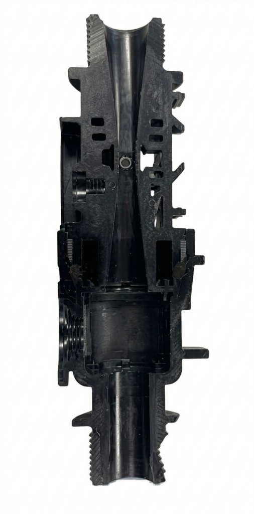
Read the full case study: RF Welding Enables a 40% Glass-Filled PPS Water Metering Valve.
Emabond RF Welding vs. O-Rings, Screws, and Adhesives at the Pump or Valve Body Joint
The right choice depends on the product. Many housings use a weld at the permanent body joint and mechanical seals at serviceable connections.
| Approach | Where it fits | What to weigh at the body joint |
|---|---|---|
| Screws or bolts with an O-ring or gasket | Joints that must be opened for service. | Flange size and stiffness, fastener count and torque control, and seal compression set over time. |
| Adhesive bonding | Material pairs or geometries suited to bonding. | Surface preparation, bond-line control, cure time and work-in-process, and fluid and temperature resistance. |
| Ultrasonic, vibration, or hot plate welding | Established processes for many housings. | Part motion or tool contact at the joint, flash management, and reach on 3D weld paths. |
| Laser welding | Parts with a laser-transmissive upper component and line-of-sight access. | Optical properties of filled or colored grades and joint fit-up. See Laser Welding vs. Emabond. |
| Emabond RF welding | Permanent sealed joints, filled and engineering resins, 3D paths, and dissimilar materials. | Joint design for the joining material, coil access, fixture support, and joining-material cost. |
Frequently Asked Questions
Can a welded joint replace the O-ring and bolts on a plastic pump or valve body?
Yes, at a permanent body joint. A validated continuous Emabond weld can provide both the structural connection and the seal, removing the flange, fasteners, and gasket at that joint. Ports, shaft seals, and serviceable covers may still need their own seals.
How much pressure can a welded plastic pump housing hold?
It depends on the resin, the joint design and size, the housing stiffness, and temperature and time under load. Estimate the separating force on the seam early, then establish capability with proof, burst, and pressure-cycling tests on the complete housing rather than weld coupons.
Can Emabond weld near metal inserts, shafts, or motor magnets?
Often, yes. Heat is generated at the joint, but metal in or near the RF field can absorb energy, so coil position and spacing to metal parts are reviewed in CAD. When a PCB or sensor sits very close to the weld line, a short lab trial confirms the components are unaffected.
Will weld flash get into the impeller or valve seat?
The joint is designed with a controlled space for displaced melt, away from impeller clearances, seats, and flow passages. Early welded parts are sectioned to confirm that melt stays where it was designed to go.
Do we need a prototype phase before production?
Usually not. When the joint is designed with Emabond from the start, most programs go directly to production fixtures, coils, and process development. A lab trial is recommended mainly for carbon-filled resins, dissimilar materials, or electronics very close to the weld line, and some teams choose in-depth trials as their own preference.
Can glass-filled nylon, PPS, or PBT pump housings be welded?
Yes. Emabond welds filled engineering resins every day, including grades with high glass content. One example is a water metering valve molded in 40% glass-filled PPS that meets a 1,000 psi burst requirement and a 350 psi cyclic leak test. Feasibility and joint strength depend on the exact production grade, so evaluations use your production materials.
When should we contact Emabond about a pump or valve housing?
As early as the concept CAD, and before the mold design is released. That is when joint geometry, melt space, insert positions, and fixture surfaces can still be changed easily.
Start a Design Review with Emabond
If you are designing or converting a pump body, valve housing, manifold, or other fluid-handling assembly in thermoplastic, bring it to us while it is still in CAD. Send a short description, the material grades, your current or planned joining method, and the primary sealing or strength requirement. A model or drawing helps, and we routinely work under NDA. We will review the joint concept with your team and map out the path to production, including a lab trial if your application or your team calls for one.
Contact Emabond to start a design review of your pump or valve housing.
Related Engineering Resources
- Metal-to-Plastic Conversion: Welding and Sealing Thermoplastic Assemblies
- Plastic Welding for Large and Complex Assemblies
- How to Achieve IP67/IP68 Seals in Plastic Enclosures Without Gaskets
- Emabond Joint Design
- How Emabond Welding Works